1.5.3. Main window and menu options
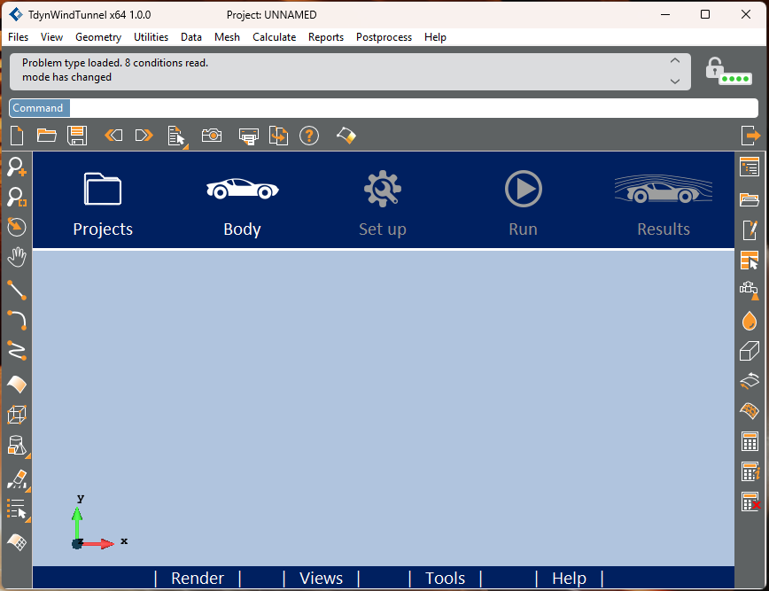
This chapter describes the Tdyn Wind Tunnel main window and the menu options it contains.
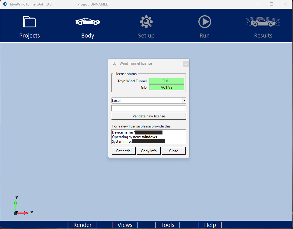
Fig. 1.104 Main window of Tdyn Wind Tunnel. Each button provides access to its corresponding menu.
1.5.3.1. Projects menu
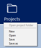
Fig. 1.105 Menu Projects: It allows to manage Wind Tunnel projects.
This menu allows to create new projects, open created projects, and save projects after their creation.
This menu allows for the creation of new projects, opening of existing projects, and saving of projects once they have been created.
1.5.3.2. Body menu
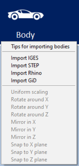
Fig. 1.106 Menu Body: It allows to import geometry from IGES, Rhino and STEP files and apply some movement operation as rotations and mirrors
This menu provides the capability to import geometry from IGES, Rhino, STEP and GiD files and perform movement operations such as rotations and mirrors.
The movement operations are only accessible when geometry from IGES or another opened project is present.
This geometry can be created using software applications like GiD, Rhinoceros, or any other CAD application that supports IGES export functionality.
A plugin is available to facilitate the export of geometry from Rhinoceros and import it into Tdyn Wind Tunnel.
If a new geometry has been imported, the previous geometry is replaced with the new one.
1.5.3.2.1. Geometry criteria
- To perform a wind tunnel simulation, the geometry should fulfill the following criteria:
The body is expected to be be facing in the -X direction, as the wind moves in the +X direction.
The vertical reference of the body must be aligned with the Z direction.
The geometry must be expressed in meters.
If any symmetry (Y or Z) is used, then the body must be located Y=0 and/or Z=0. Otherwise, symmetry options are not available.
The volume of the geometry’s bounding box must be greater than 10-3and less than 106. Otherwise, a warning message appears for the user to verify the correctness of the geometry units. However, it is not mandatory to modify the dimensions of the geometry.
The geometry must consist of one or more volumes or a set of surfaces that enclose one or more volumes.
All these criteria are explained in Body >> Tips for importing bodies.
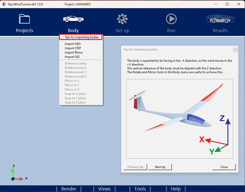
Fig. 1.107 Body >> Tips for importing bodies: It shows some tips about the geometry criteria should fulfill.
1.5.3.2.2. Importing simple figures of revolution
When a simple figure of revolution, such as a sphere, is imported into Tdyn Wind Tunnel, it may not be imported correctly.
Simple revolution geometries (like cylinders and spheres), are sometimes oversimplified during their creation, resulting in volumes with the minimum possible number of surfaces, but without enough information. This makes it mathematically difficult, if not impossible, to perform the intersection and subtraction operations required to obtain the air domain, which leads to warnings during the import process or errors when meshing.
To illustrate this with an example, consider a simple cylinder. Many CAD programs generate 3 surfaces: bottom, top, and side. Each of these is also defined by its boundary lines, where the side surface will have 3 lines: a bottom circle, a top circle, and a vertical line. The problem is immediately apparent, a surface that starts and ends with the same line.
The workaround is to divide the body into two or more parts so that none of the revolved surfaces does so for a full revolution.
1.5.3.3. Set-up menu
Fig. 1.108 Menu Set-up: It opens Set-up panel to define the necessary parameters for wind tunnel definition.
This option is only activated when the model’s geometry has been imported using the previous menu.
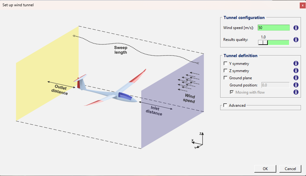
Fig. 1.109 Set-up panel. Each parameter includes a tooltip providing additional information about it.
After defining all the parameters and pressing the ‘OK’ button, the virtual tunnel environment is created to perform the simulation.
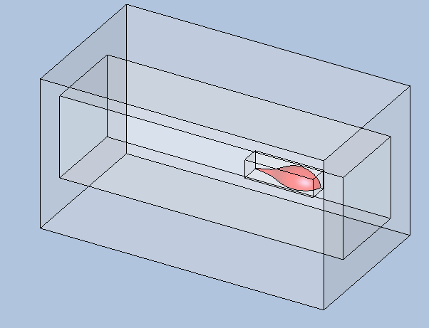
Fig. 1.110 Virtual tunnel environment
1.5.3.4. Run menu
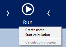
Fig. 1.111 Menu Run: It enables the creation of the model’s mesh, execution of the simulation, and display of the calculation progress.
1.5.3.4.1. Create mesh
Before executing the calculation, it is necessary to create the mesh of the wind tunnel geometry and virtual environment. In case the menu option ‘Start calculation’ is executed, then the mesh is automatically created before running the simulation.
For some models with complex geometry, the following error may occur during mesh generation.
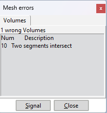
Fig. 1.112 This error message appears when the geometry is so complex that mesh cannot be created.
To correct this error, it is necessary to open the Set-up window and increase the value of the Results quality parameter. When the value of this parameter is increased, the resulting mesh will be finer. Once the parameter has been modified, the mesh must be created again and check that the previous error is corrected.
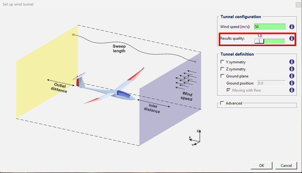
Fig. 1.113 Results quality: Increasing this parameter will result in a finer mesh.
1.5.3.4.2. Start calculation and Calculation progress
Once the mesh has been generated it is possible to run the simulation using the corresponding menu item. The Calculation Progress window will then appear.
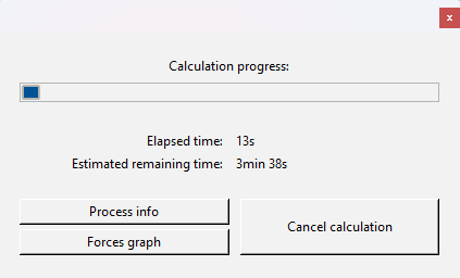
Fig. 1.114 Calculation progress window: Shows the elapsed and estimated remaining time. It is also possible to open the Process info and Forces graph windows.
1.5.3.5. Results menu
Fig. 1.115 Results menu: It opens the postprocess interface where results can be shown.
This option is available when a simulation is running or finished. It opens the postprocess interface where results can be displayed.
1.5.3.6. Render menu
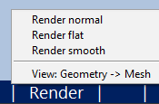
Fig. 1.116 Render Menu: It provides options to choose from various render types and displays the model’s mesh.
A display of all available render types and the mesh view below.

Fig. 1.117 A view of all available renders in geometry mode and mesh mode.
1.5.3.7. Views menu
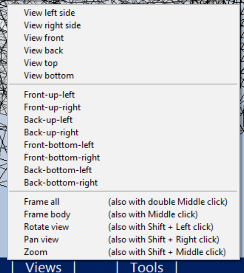
This menu option contains different default views and allows zooming, panning and rotating the view camera.
1.5.3.8. Tools menu
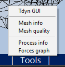
Fig. 1.118 Tools Menu: It allows access to the complete Tdyn interface and provides information on the mesh and the calculation process.
Tdyn GUI: It opens or close Tdyn interface.
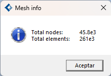
Mesh info: If a mesh is present, it displays the number of nodes and elements of mesh.
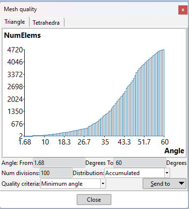
Mesh quality: If a mesh is present, a dialog box displaying mesh quality information will appear.
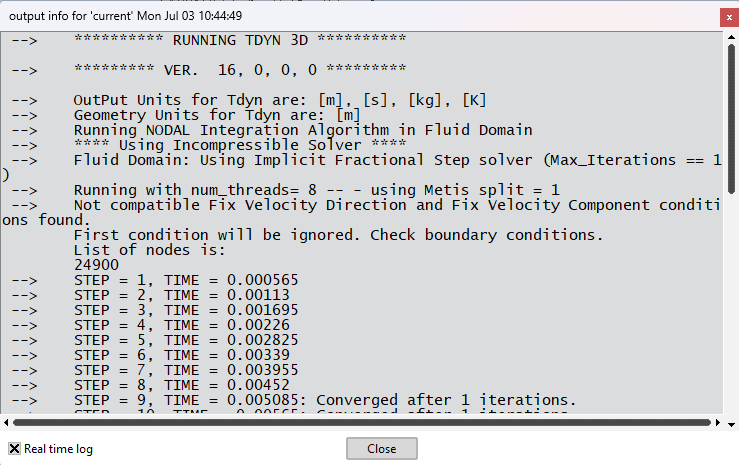
Process info: When a calculation is in progress or has been completed, a window is displayed with information about the calculation process. Here it can be seen the step currently being calculated, the time associated with that step, and if the numerical convergence has been achieved or not. It is normal not to reach convergence during the first steps.
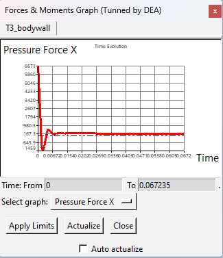
Forces graph: When a calculation is in progress or has been completed, a window is displayed showing a graph of the time evolution of the forces and moments acting on the objects under analysis. These forces and moments are obtained by integrating the forces due to dynamic pressure, static pressure, and viscosity over the surfaces of the object. They are provided as their Cartesian components. These plots are used to assess what is usually referred to as the convergence of the simulation, i.e., if all the resultant forces tend to a stable value, then it is likely that the solution available at that moment is accurate enough. On the other hand, if a stable value can’t be reached, it is a good practice to allow more steps to be calculated. If this is seen after the calculation process is finished, it is required to increase the value of Sweep length in the wind tunnel set up and repeat the calculation. It is normal to find oscillations during the first steps.
1.5.3.9. Help menu
Fig. 1.119 Help menu: It allows to enter passwords and give access to Compass website, User’s manual and Video tutorial.