1.1. Getting started

The aim of the Tdyn Getting Started manual is to help users to start using all Tdyn capabilities quickly. To this aim, the main components of the Tdyn graphic user interface (GUI) are introduced in detail. The user will make extensive use of these components while preparing simulation models. Hence, It is essential to acquire a good knowledge on how to use these tools in order to rapidly increase the productivity.
The two main components of the Tdyn GUI that are going to be presented in this manual are:
The Start Data window
The Tdyn Data tree
1.1.1. The Start Data window
When the user starts Tdyn for the first time, he/she faces off with the Start Data window shown here.
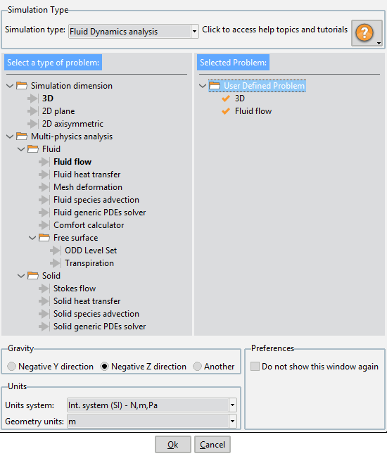
Start Data window as it is shown to the user the first time it starts Tdyn
The icon at the top right corner of the window provides access to the various Help topics and Tutorials of Tdyn. By clicking the icon, the following list of available topics appears:
Getting started
Tdyn CFD+HT tutorials
RamSeries tutorials
SeaFEM tutorials
Preprocessor tutorials
Online support
The user can select any of this options in order to open the corresponding topic manual.
The Start Data window aims to simplify the GUI of Tdyn and to accommodate it to the type of simulation that is going to be undertaken. Actually, the Start Data window is used to define the GUI features that may concern the case study and to hide all those components that are not necessary for the problem at hand.
The first step to specify which GUI components will be available during the working session of Tdyn, is to select the type of problem that is going to be simulated. This is done by selecting a Simulation type from the list box at the top right corner of the Start Data window.
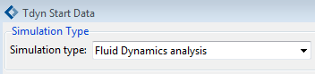
Fig. 1.1 List box used to select the Simulation type
The list of Simulation types available reads as follows. You can follow the links to obtain specific information on each type of simulation.
Fluid Dynamics analysis
Structural analysis
Seakeeping analysis
Multiphysics analysis
Coupled Seakeeping-Structural analysis
Thermomechanical analysis
Fluid-Structure interaction analysis
Once the simulation type has been chosen, all capable options in the context of the problem under analysis appear on the left panel of the Start Data window. The user can start to select among these components in order to compose a valid problem configuration. The user’s selection appears on the right panel.
To select a component, double-click on the corresponding option within the left panel.
To remove a previously selected component, double-click on the corresponding option within the right panel.
The Start Data window is able to control if the user has already selected the minimum components required to run a case of the given simulation type. If this is not the case, missing components are highlighted in red on the left panel, and a warning message appears next to the option’s selection and cancel buttons. See for instance the image below:
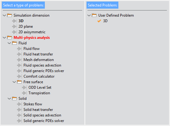
Fig. 1.2 Start Data window showing a non-valid problem configuration
At least one option from each highlighted section of the data tree must be selected to be able to proceed with the simulation.
Once a viable problem has been configured, the warning message disappears and no highlighted entries remain within the left panel. See for instance the figure below corresponding to the most basic case of a fluid dynamics analysis simulation type.
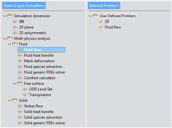
Fig. 1.3 Start Data window showing a valid problem configuration for the most basic type of CFD analysis
Before leaving the Start Data window and proceed to the Tdyn working area, basic general properties of the simulation can be defined at the bottom panel of the Start Data window. Such basic options are:
Gravity direction
Units system to be used during the analysis
Geometry units
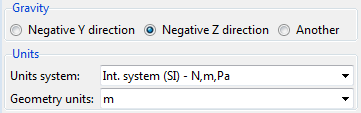
Fig. 1.4 General properties selection panel
Finally, press the Ok button to proceed to the working area of Tdyn.
1.1.1.1. Fluid Dynamics analysis
All the options available for the Fluid Dynamics analysis simulation type are shown in the figure bellow as they appear within the Start Data window.
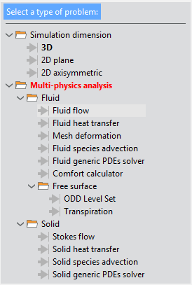
Fig. 1.5 Available options for Fluid Dynamics analysis type of simulation
As indicated in red, at least one option from the Multi-physics analysis section, either for fluids or solids, must be selected in order to have a valid configuration of the CFD problem.
1.1.1.2. Structural analysis
All the options available for the Structural analysis simulation type are shown in the figure bellow as they appear within the Start Data window.
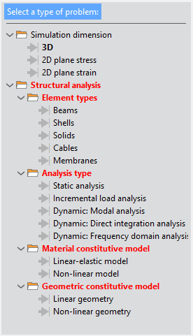
Fig. 1.6 Available options for the Structural analysis type of simulation
As indicated in red, several options concerning the type of structural element, the type of analysis, and the material and geometric constitutive models must be selected to define a valid problem for this type of simulation.
1.1.1.3. Seakeeping analysis
All the options available for the Seakeeping analysis simulation type are shown in the figure bellow as they appear within the Start Data window.
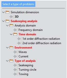
Fig. 1.7 Available options for Seakeeping analysis type of simulation
As indicated in red, several options concerning the type of analysis and sea state environment must be selected to define a valid problem for this type of simulation.
1.1.1.4. Multiphysics analysis
All the options available for the Multiphysics analysis simulation type are shown in the figure bellow as they appear within the Start Data window.
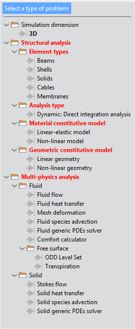
Fig. 1.8 Available options for the Multiphysics analysis type of simulation
As you can appreciate, the Multiphysics analysis simulation type combines all the options of the Fluid Dynamics analysis with only those options of the Structural analysis that are actually compatible.
1.1.1.5. Thermomechanical analysis
All the options available for the Thermomechanical analysis simulation type are shown in the figure bellow as they appear within the Start Data window.
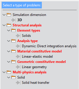
Fig. 1.9 Available options for the Thermomechanical analysis type of simulation
As you can appreciate, the Thermomechanical analysis simulation type significantly reduces the number of options available. The resulting problem configurations are specifically thought for case studies involving the coupling between the structural and the thermal phenomena occurring in solids.
1.1.1.6. Fluid-Structure interaction analysis
All the options available for the Thermomechanical analysis simulation type are shown in the figure bellow as they appear within the Start Data window.
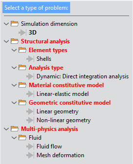
Fig. 1.10 Available options for the Fluid-Structure analysis type of simulation
As you can appreciate, the Thermomechanical analysis simulation type significantly reduces the number of options available. The resulting problem configurations are specifically thought for case studies involving the coupling between the structural behavior and the thermal phenomena occurring in solids.
1.1.1.7. Coupled Seakeeping-Structural analysis
All the options available for the Coupled Seakeeping-Structural analysis simulation type are shown in the figure bellow as they appear within the Start Data window.
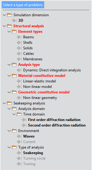
Fig. 1.11 Available options for the Coupled Seakeeping-Structural analysis type of simulation
As you can appreciate, the Coupled Seakeeping-Structural analysis simulation type combines all seakeeping capabilities of Tdyn with only those options of the Structural analysis that are actually compatible (this is the non-linear geometric dynamic analysis of structural elements).
1.1.2. The TDYN Data tree
Once the simulation type has been configured through the start data window, the user faces off with the working area of the Tdyn’s GUI. This looks similar to the image shown bellow.
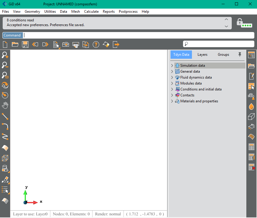
Tdyn’s GUI includes the usual preprocessing tools which are distributed within various menus and toolbars at the top and left side of the GUI.
In addition, Tdyn’s GUI provides a Data Tree that contains all the data necessary to define a simulation.
The actual data and the appearance of the data tree depends on the simulation type and problem configuration selected in the start data window. Such a selection, and consequently the appearance of the data tree, can be changed at any moment by opening the start data window through the menu option
Data >> Start data
and choosing a different simulation type, or by changing it directly through the following option in the data tree itself.
Simulation data >> Simulation type
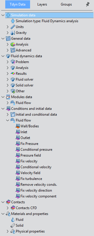
Data tree structure
A Tdyn simulation can contain a huge amount of data. To ease the user’s work, the simulation data is organized in the data tree by using a set of nested blocks of data and data containers that finally contain either groups of values or conditions to be applied to geometrical entities of the model under analysis.
Each blockdata and/or container can be expanded to see its content by left-clicking the small arrow next to the corresponding section of the data tree. By double-clicking a given section of the data tree a window is opened at the bottom of the data tree so that the user can edit the corresponding parameters.
When double-clicking a condition in the data tree, a new window is opened at the bottom of the data tree so that the user can edit the values of the parameters associated to the given condition. In this cases, the window also serves to select the geometrical entities to which the condition must be applied. The condition assignment is performed by pressing the select button shown below that appears at the bottom of the window.
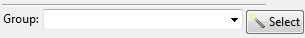
After the assignment is confirmed, a new group is created. Alternatively, condition assignment can be performed by selecting an already existent group from the drop-down list.
Groups management
A large number of conditions exists within Tdyn that need to be applied to actual geometrical entities of the model. These conditions are further transferred automatically to mesh entities (nodes and/or elements) during the meshing process so that the corresponding boundary conditions can be applied consistently during the FEM simulation process.
As explained before, the assignment of conditions is performed by selecting geometrical entities that are collected and organized in groups.
Groups can be managed by using the groups window shown below.
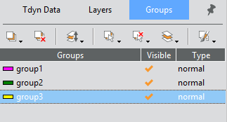
From the window above, several actions can be undertaken to manage the groups by using the icons at the bottom of the window. Some of them are summarized here:
Create new groups
Delete groups
Add entities to already existent groups
Remove entities from groups
Visualize groups and list their entities
The groups managed from the above window are further accessible within the windows used to define boundary conditions in the data tree.