1.3.10. Dynamic conditions
These options allow to define the required conditions of the dynamic analysis. This tab requires Analysis > Analysis type > Dynamic analysis.
1.3.10.1. Initial conditions
In the Linear-Dynamics and Non-Linear Dynamics analysis the Initial Conditions of the structure must be defined. These initial conditions can be applied for every degree of freedom (X, Y, Z and rotations for beams and shells), and for every node in the model Default units are meters for the X, Y and Z displacements and radians for the prescribed rotations. X Constraint, Y Constraint and Z Constraint mean the displacements along the axes. \(\theta_x\) constraint, \(\theta_y\) constraint and \(\theta_z\) constraint mean the rotations around the axes. This condition can be applied to either points, lines or in the solid analysis, to surfaces. Note: 3D solids have only three degrees of freedom: displacements in X, Y and Z.
In Fig. 1.22 shows the window for defining the initial conditions of the dynamic analysis.
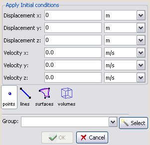
Fig. 1.22 Initial conditions window definition.
1.3.10.2. Masses
Dynamic conditions > Masses.
When performing a dynamic analysis, the mass of the structure and equipment has to be specified in order to take into account their inertial forces. The mass of the items included in the geometry of the model are calculated by the density of the material assignation (see section Materials of this manual). Therefore, those elements not modelled in the geometry have to be properly included (such as the engine of a ship). RamSeries allows to include them by the option Masses as punctual, or along a beam or shell of the model.
1.3.10.2.1. Point mass
This is a mass applied to one point of the structure, such as those which its distribution is small is comparison with the model. Default units are \(kg\) for the translation mass components and \(kg/m^2\) for the rotation mass components.
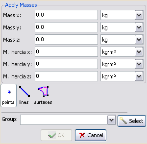
Fig. 1.23 Point mass window definition.
1.3.10.2.2. Beam mass
A beam mass is specified when considering the distributed mass of a beam. These option allows to include masses distributed along a beam. Default units are \(kg/m\) for translation mass and \(kg·m\) for rotational mass.
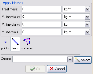
Fig. 1.24 Beam mass window definition.
Note: if this condition is applied over a line which is contour of a shell but has not got beam properties assigned, it will automatically considered as a shell-boundary mass.
1.3.10.2.3. Surface shell mass
This is a mass applied to a shell element of the structure. These option allows to include masses distributed along a surface. Default units are \(kg/m^2\).
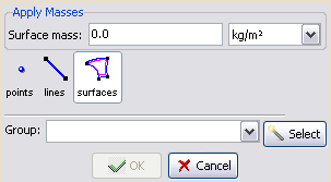
Fig. 1.25 Shell mass window definition.