1.6.3. Main window and menu options
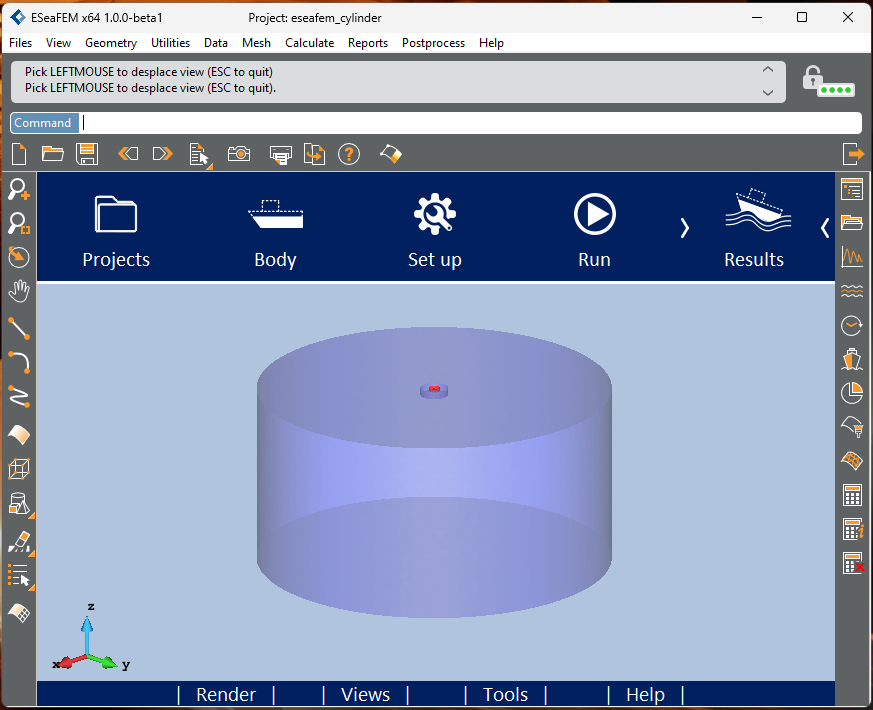
This chapter describes the E-SeaFEM main window and the menu options it contains.
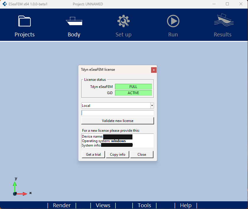
Fig. 1.130 Main window of E-SeaFEM. Each button provides access to its corresponding menu.
1.6.3.1. Projects menu
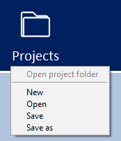
Fig. 1.131 Menu Projects: It allows to manage E-SeaFEM projects.
This menu allows to create new projects, open created projects, and save projects after their creation.
This menu allows for the creation of new projects, opening of existing projects, and saving of projects once they have been created.
1.6.3.2. Body menu
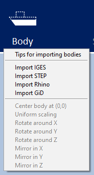
Fig. 1.132 Menu Body: It allows to import geometry from IGES, Rhino, STEP and GiD files and apply some movement operation as rotations and mirrors
This menu provides the capability to import geometry from IGES, Rhino, STEP and GiD files and perform movement operations such as rotations and mirrors.
The movement operations are only accessible when geometry from IGES or another opened project is present.
This geometry can be created using software applications like GiD, Rhinoceros, or any other CAD application that supports IGES export functionality.
A plugin is available to facilitate the export of geometry from Rhinoceros and import it into E-SeaFEM.
If a new geometry has been imported, the previous geometry is replaced with the new one.
1.6.3.2.1. Geometry criteria
To perform a simulation with E-SeaFEM, the geometry should fulfill the following criteria:
The vertical reference of the body must be aligned with the Z direction.
The incoming waves move in the -X direction.
The geometry are expected in meters.
Import only the submerged part or the body, as a solid volume.
It must represent the volume of water displaced by the whole object.
Do not use geometries that only model the skin or hull.
After importing or modifying the body (rotation, scale or mirror), it will automatically be placed with the top at Z=0.
All these criteria are explained in Body > Tips for importing bodies.
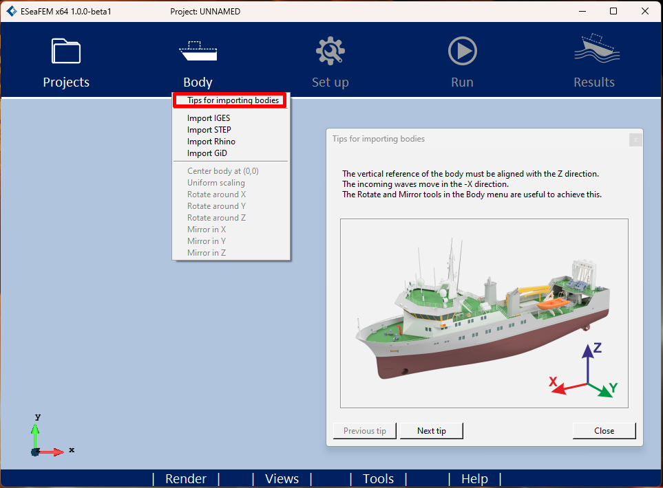
Fig. 1.133 Body > Tips for importing bodies: It shows some tips about the geometry criteria should fulfill.
The Rotate, Mirror and Uniform scaling tools, availables in Body menu, are useful to fulfill the geometry criteria.
1.6.3.2.2. Importing simple figures of revolution
When a simple figure of revolution, such as a sphere, is imported into Tdyn Wind Tunnel, it may not be imported correctly.
Simple revolution geometries (like cylinders and spheres), are sometimes oversimplified during their creation, resulting in volumes with the minimum possible number of surfaces, but without enough information. This makes it mathematically difficult, if not impossible, to perform the intersection and subtraction operations required to obtain the air domain, which leads to warnings during the import process or errors when meshing.
To illustrate this with an example, consider a simple cylinder. Many CAD programs generate 3 surfaces: bottom, top, and side. Each of these is also defined by its boundary lines, where the side surface will have 3 lines: a bottom circle, a top circle, and a vertical line. The problem is immediately apparent, a surface that starts and ends with the same line.
The workaround is to divide the body into two or more parts so that none of the revolved surfaces does so for a full revolution.
1.6.3.3. Set-up menu
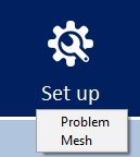
Fig. 1.134 Menu Set-up: It allows to open Set-up Problem panel to define the necessary parameters for seakeeping analysis definition. It also allows to open Set-up Mesh to define the maximum element size for each region of domain.
Set-up menu is only activated when the model’s geometry has been imported using the previous menu.
Set-up > Problem: It allows to define the computational domain (beach, depth, etc…), the waves (monochromatic waves, Pierson Moskowitz and Jonswap) and the body (center of gravity, radii of gyration, etc…).
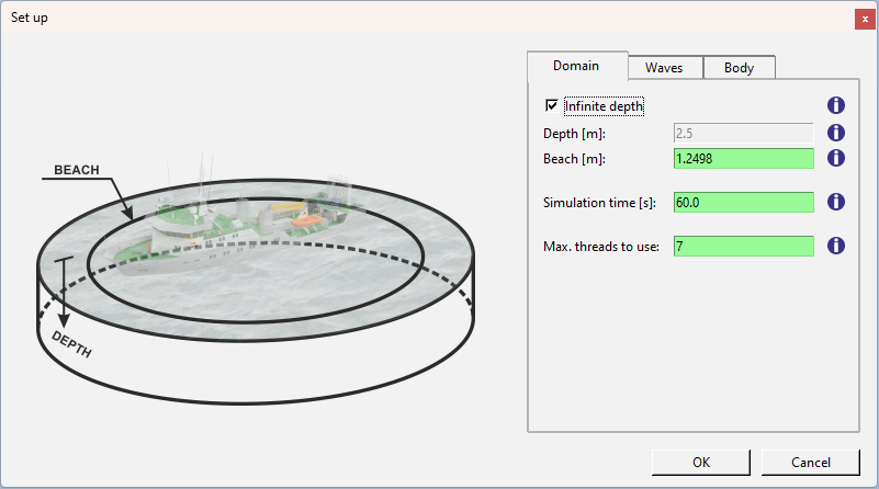
Fig. 1.135 Set-up panel. Each parameter includes a tooltip providing additional information about it.
After defining all the parameters and pressing the ‘OK’ button, the computational domain is created to perform the simulation and Set-up > Mesh is enabled.
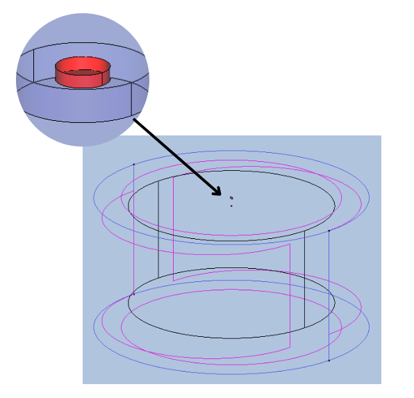
Fig. 1.136 Seakeeping and model domain.
Set-up > Mesh: This option is available after using Set-up > Problem and computational domain is defined. It allows to define the maximum element size for each region of the computational domain (body, free surface, etc…) and to mesh multiple regions of the domain.
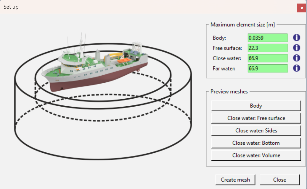
Fig. 1.137 Set-up mesh of computational domain and model.
1.6.3.4. Run menu
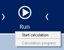
Fig. 1.138 Menu Run: It enables the execution of the simulation, and display of the calculation progress.
Once the mesh has been generated it is possible to run the simulation using the corresponding menu item. The Calculation Progress window will then appear.
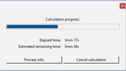
Fig. 1.139 Calculation progress window: Shows the elapsed and estimated remaining time. It is also possible to open the Process info.
1.6.3.5. Results menu
Fig. 1.140 Results menu: It opens the postprocess interface where results can be shown.
This option is available when a simulation is running or finished. It opens the postprocess interface where results can be displayed.
1.6.3.6. Render menu
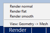
Fig. 1.141 Render Menu: It provides options to choose from various render types and displays the model’s mesh.
A display of all available render types and the mesh view below.
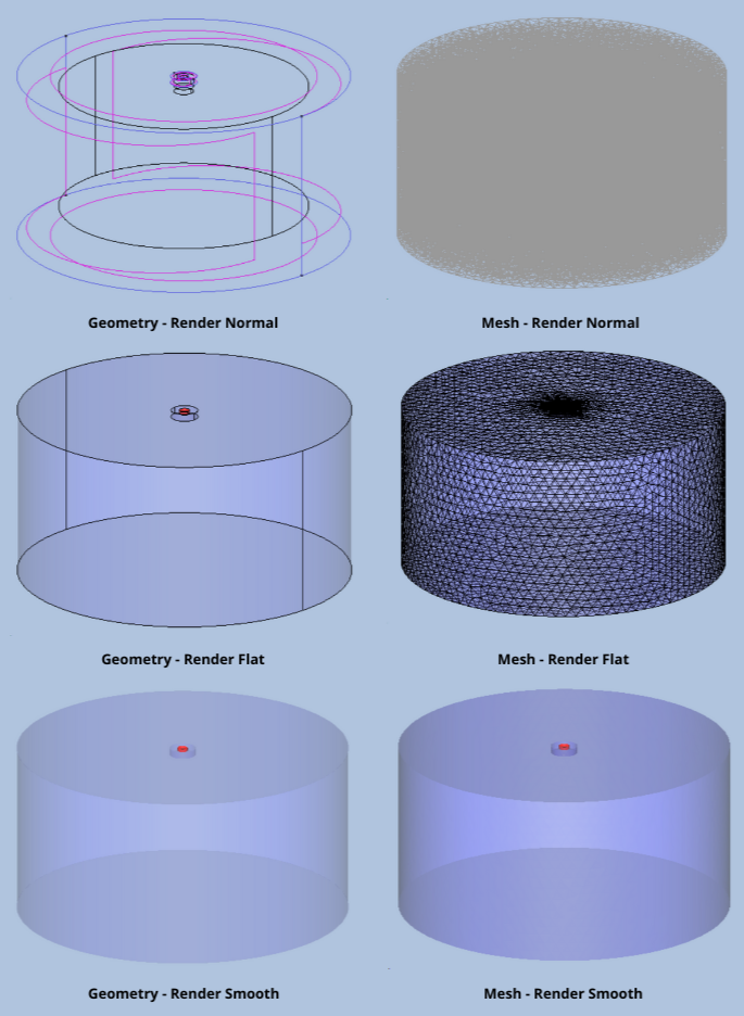
Fig. 1.142 A view of all available renders in geometry mode and mesh mode.
1.6.3.7. Views menu
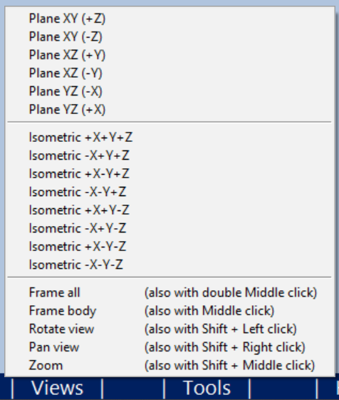
This menu option contains different default views and allows zooming, panning and rotating the view camera.
1.6.3.8. Tools menu
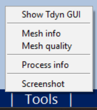
Fig. 1.143 Tools Menu: It allows access to the complete Tdyn SeaFEM interface and provides information on the mesh and the calculation process.
Tdyn GUI: It opens or close Tdyn SeaFEM interface.
From the Tdyn SeaFEM interface it is possible to use all the advanced capabilities of SeaFEM such as second order effects, inter-body connections, etc…
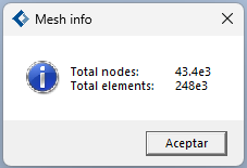
Mesh info: If a mesh is present, it displays the number of nodes and elements of mesh.
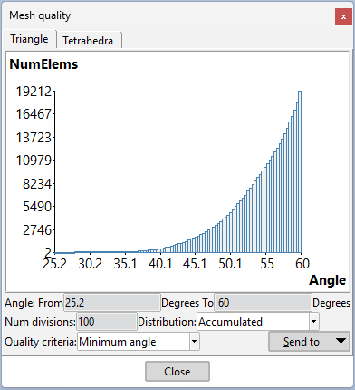
Mesh quality: If a mesh is present, a dialog box displaying mesh quality information will appear.
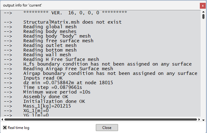
Process info: When a calculation is in progress or has been completed, a window is displayed with information about the calculation process. Here it can be seen the step currently being calculated, the time associated with that step, and if the numerical convergence has been achieved or not.
1.6.3.9. Help menu
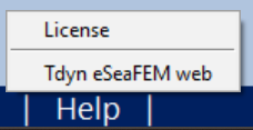
Fig. 1.144 Help menu: It allows to enter passwords and give access to Compass website and user’s manual.