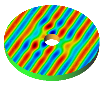
A simple example: the bottom mounted cylinder
model case

This tutorial will guide you through the basic steps to create a CAD/CAE model for the numerical analysis of a seakeeping problem. Geometry generation tools, boundary conditions assignment, calculation and results visualization will be addressed within the context of a simple problem consisting on a cylindrical structure fixed to the bottom of the sea.
Geometry definition
In this section, we will describe in detail the geometry generation process. SeaFEM has plenty of tools for geometry generation. Hence, the way to construct the geometry that is shown in this tutorial may constitute just one of many possibilities. For a more detailed description of geometry generation tools and other pre-processing capabilities of SeaFEM, we strongly recommend the user to take a look at the GiD pre-processing manual (see http://www.gidhome.com/support). For the present case, both the body and the computational domain are cylindrical, and therefore they can be easily created by means of the geometry generation tools available in the GUI of SeaFEM. Before starting to construct the geometry, it is important to remark that the entire computational domain in SeaFEM must be located below the undisturbed water surface (i.e z? 0). In the present case, the domain will be also centered at the origin (0,0,0).
Before starting to construct the geometry, few general advertisements become pertinent:
For the cases where no currents are imposed, the most indicated shape for the computational domain is a cylinder. The computational depth should be no larger than the physical depth. Moreover, computational depth might be smaller than physical and/or recommended depth if the bottom boundary condition is used.
A region with higher mesh resolution is usually needed close to the floating object in order to correctly capture the scattered waves solution (waves radiated and difracted by the floating object). In the present case, the border of this area will coincide with the beginning of the damping/absorption area (beach), although this is not mandatory in general. Actually, the absorption area should be at least as long as the maximum wave length, although the recommended length is twice the maximum wave length. Nevertheless, if monochromatic wave is used along with Sommerfeld radiation condition, the absorption area might be reduced to half the wave length.
To further facilitate boundary conditions assignement and many other pre-processing operations, it is advisable to organize the geometry by layers.
Now, one of the several possible ways for generating the geometry of the present tutorial will be explained. Simply follow the steps in the given order.
First we proceed to create the bottom surface of the entire computational domain.
Open the layers window and rename the existing layer to domain_contour.
Utilities > Layers
Right click on the layer named Layer0
Select the Rename option
Enter the name of the new layer (i.e. domain_contour).
Create the bottom boundary of the computational domain. It consists of a circle located at z = -1.0 m. and of radius R = 6.0 m.
Enter center: 0 0 -1
Enter normal: Positive Z
Enter radius: 6.0
Create a new layer called Body.
Right click on the layers window
Select the New layer option
Enter the name of the new layer (i.e. Body).
Create a circle representing the base of the body.
Enter center: 0 0 -1
Enter normal: Positive Z
Enter radius: 1.0
Delete the surface of the bottom mounted cylinder to retain just the lines that define the perimeter of the body.
Select the surface of the bottom mounted cylinder
Generate a hole within the NURBS surface corresponding to the bottom boundary of the computational domain.
Enter surface: Select the domain bottom boundary suface.
Enter lines to define the hole:Select the lines that define the base of the bottom mounted cylinder.
Up to this point, the gometry of the model should look like the figure below.
Create the lateral boundary of the computational domain. It can be simply created by extrusion of the lines delimiting the outter bottom boundary.
Entity type: Lines
Transformation: Translation
First point: 6.0, 0.0, -1.0
Second point: 6.0, 0.0, 0.0
Do extrude: Surfaces
Select the lines that define the outter perimeter of the domain’s bottom surface
Create the inner lateral boundary of the computational domain, which coincides with the wall of the bottom mounted cyliner. As in the prvious step, this can be done by copying and extruding the inner and outer lines of the domain’s bottom surface.
Entity type: lines
Transformation: Translation
First point: 6.0, 0.0, -1.0
Second point: 6.0, 0.0, 0.0
Do extrude: Surfaces
Select the lines that define the perimeter of the cylinder’s base
After this, the geometry of the computational domain should look similar to what is shown in the following figure.
Create a new layer called free_surface.
Right click on the layers window
Select the New layer option
Enter the name of the new layer (i.e. free_surface)
Create the perimeter of the analysis area.
Enter center: 0 0 0
Enter normal: Positive Z
Enter radius: 2.0
Delete the created surface to retain just the lines
Create the free surface analysis area.
Select the lines that define both, the inner and outter boundaries of the free surface analysis area.
13. Create the free surface absorption area. - Select the lines that define both, the inner and outter boundaries of the absorption area.
Create a new layer named volumes
Right click on the layers window
Select the New layer option
Enter the name of the new layer (i.e. volumes).
Create a volume encompassing the entire computational domain
Select all the surfaces of the model.
The final geometry should look similar to what is shown in the next image: